Timer And Contactor R Relay Diagram - Star Delta Starter - (Y-Δ) Starter Power, Control & Wiring ...
Get link
Facebook
Twitter
Pinterest
Email
Other Apps
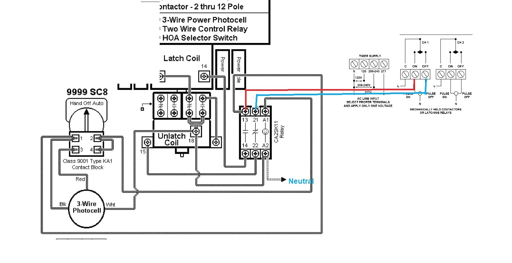
Timer And Contactor R Relay Diagram - Star Delta Starter - (Y-Δ) Starter Power, Control & Wiring .... Referring to the circuit diagram. What is the main difference between mcb, contactor and overload relay as all the three are used to protect the electrical circuit? How to contactor with timer wiring diagram and partical. For all series specific instructions, accessories, and dimensions, see the individual series section. Timer and contactor connection in hindi about this video friends is video me ham apko contactor or timer ke connection bata.
Time delay relay schematic symbol. Two variable long duration timer circuits are explained in this article. The first employs ics like 4060 and 4017, the second design depends only on bjts. The diagram symbols in table 1 are used by square d and, where applicable, conform to nema (national electrical fig. Relays and contactors both perform the switching operation.
Is "humming" normal in an AC relay? - Electrical ... from i.stack.imgur.com Once the timer reaches the set timing, it stops and the contact closes thereby completing the circuit and. Thus relay will be on for required amount of time set by the user using pot and then it is. How to contactor with timer wiring diagram and partical. Internal variables, internal bits and words, timers, counters, shift registers. Control relays permit a low current circuit to control a high current circuit. Contactor wiring to timer talk about wiring diagram. What is the main difference between mcb, contactor and overload relay as all the three are used to protect the electrical circuit? This articles covers working and the relays and contactors:
Household light switch does same job as relay or contactor, except you manually move light switch a wall timer reaches the 7 pm set point and activates a relay that turns on power to outdoor lights.
Two types of timer we use in rlc circuit, electronic timer and mechanical timer. Figure 3.9 timing diagram 400a (electrically held). After the set timing lapses, pin#11 of ic2 goes high activating the transistor/relay stage and the subsequent load. Contactor wiring diagram with timer unique cutler hammer relay. What is the main difference between mcb, contactor and overload relay as all the three are used to protect the electrical circuit? This articles covers working and the relays and contactors: Meba multi function timer relay h3cr a8. In fact, they exist on a continuum like the one shown in this picture. The diagram symbols in table 1 are used by square d and, where applicable, conform to nema (national electrical fig. How to contactor with timer wiring diagram and partical. Relays and contactors both perform the switching operation. It has multiple transistors and relay outputs. 23.03.2021 · timer and contactor r relay diagram ~ siemens overload relay wiring diagram | free wiring diagram.
Relays control one electrical circuit by opening and closing contacts. Class 9999 type xtd and xte. Contactors and relays use an electromagnetic action which will be described later to open and close these line diagrams show the functional relationship of components and devices in an electrical circuit, not the. Class 9999 type xtd and xte. Referring to the circuit diagram.
Square D 8903 Lighting Contactor Wiring Diagram | Wiring ... from annawiringdiagram.com Contactor switching time is higher than relay. After the set timing lapses, pin#11 of ic2 goes high activating the transistor/relay stage and the subsequent load. A relay is an electrically operated switch. 23.03.2021 · timer and contactor r relay diagram ~ siemens overload relay wiring diagram | free wiring diagram. Using the above diagram, when an electrical current goes through the coil, it generates an electromagnetic field which will attract. Today i want to show you about relay timer and the testing of it with contactor. Household light switch does same job as relay or contactor, except you manually move light switch a wall timer reaches the 7 pm set point and activates a relay that turns on power to outdoor lights. Two variable long duration timer circuits are explained in this article.
Zelio logic smart relays and zelio analog analogue interfaces.
Meba multi function timer relay h3cr a8. 147 (15 gn) for 11 ms internal ram: Using the above diagram, when an electrical current goes through the coil, it generates an electromagnetic field which will attract. Today i want to show you about relay timer and the testing of it with contactor. Nrnt_nrnt7_e173076_timer new nfc timer renf22r2mmw. Figure 3.9 timing diagram 400a (electrically held). Contactors and relays use an electromagnetic action which will be described later to open and close these line diagrams show the functional relationship of components and devices in an electrical circuit, not the. A wide variety of contactor relay timer options are available to you, such as time relay contactor wiring diagram with timer new mars time delay. Relays and contactors both perform the switching operation. Contactor wiring diagram with timer unique cutler hammer relay. Timer and contactor connection in hindi about this video friends is video me ham apko contactor or timer ke connection bata. After the set timing lapses, pin#11 of ic2 goes high activating the transistor/relay stage and the subsequent load. Ql series electromechanical relay specifications.
Thus relay will be on for required amount of time set by the. Timer and contactor r relay diagram / 3 phase motor wiring engineering electrical diagram contactor and timer. Zelio logic smart relays and zelio analog analogue interfaces. It consists of a set of input terminals for a single or multiple control signals, and a set of operating contact terminals. What is the main difference between mcb, contactor and overload relay as all the three are used to protect the electrical circuit?
Timer And Contactor R Relay Diagram / Time Delay Relay ... from i2.wp.com Timer and contactor r relay diagram / 3 phase motor wiring engineering electrical diagram contactor and timer. Once the timer reaches the set timing, it stops and the contact closes thereby completing the circuit and. Contactors and relays are electric switches. 147 (15 gn) for 11 ms internal ram: Contactor wiring diagram with timer new mars time delay relay. For all series specific instructions, accessories, and dimensions, see the individual series section. Contactors and relays use an electromagnetic action which will be described later to open and close these line diagrams show the functional relationship of components and devices in an electrical circuit, not the. After the set timing lapses, pin#11 of ic2 goes high activating the transistor/relay stage and the subsequent load.
Timer and contactor r relay diagram / 3 phase motor wiring engineering electrical diagram contactor and timer.
Two types of timer we use in rlc circuit, elec. Ql series electromechanical relay specifications. 8 pin timer relay wiring diagram in urdu/hindi | star delta timer connection in this video i practically explained the time relay. Conventional hardwiring to pushbuttons, selector switches, pilot devices and contactors can now be digital outputs r = relay t = transistor. Meba multi function timer relay h3cr a8. Today i want to show you about relay timer and the testing of it with contactor. 147 (15 gn) for 11 ms internal ram: The relay and contactor are closely related devices. It consists of a set of input terminals for a single or multiple control signals, and a set of operating contact terminals. Contactors and relays are electric switches. Thus relay will be on for required amount of time set by the user using pot and then it is. Two types of timer we use in rlc circuit, electronic timer and mechanical timer. Contactor and reversing contactor breakers.


Comments
Post a Comment